|
Outdoor load disconnectors, produced in
accordance with the Driescher company´s documentation,
used for several years on high-voltage long-distance lines,
have proven their high reliability and safety of operation.
Load disconnectors are intended particularly for terminal
branchings in radial arrangement.
Load disconnectors satisfy standards IEC 129, IEC 694
and IEC 420. Using insulators satisfy the third grade
of contmination area according.
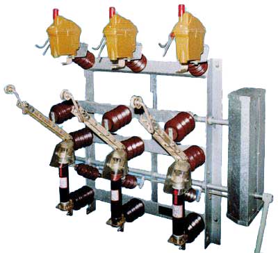
Simple load disconnectors of a sturdy structure proved
themselves in an excellent way under very different climatic
conditions.
The foundation welded frame is made of open steel profiles
which guarantee perfect surface protection from corrosion
caused by heat zinc coating that can be controlled on
all places. The shafts of the load disconnectors mounted
in bronze bearings as well as all other steel components
are protected by heat zinc coating, too.
Switching takes place in a tightly closed extinguishing
chamber, filled either with Shell Diala D transformer
oil or biologically degradable Shell FLUID 4600 transformer
oil.
With regard to this fact, Fla type load disconnectors
meet the extreme environmental requirements.
The biological degradation ability of the Shell FLUID
4600 oil was tested and is guaranted by the Deutsche Shell
AG company. Measurements were carried out in accordance
with the international methodics CEC-L-33-A.93.
All current conduction components are made of silver plated
electrolytical copper and constitute a loopless current
conduction path.
The cross-section of the conductors on the current conduction
path is sufficiently dimensioned. Appropriate contact
pressures of the stainless steel springs ensure optimum
prerequisites for faultless switching even after several
years of the load disconnector operation under extreme
operating conditions as well as under load.
The load disconnectors are delivered with such made of
a cyclo-aliphatic resin or porcelain bearings.
The load disconnectors can be provided with earthing switches
located on the under side. The use of earthing switches
requires a double or triple drive with a sturdy blocking
mechanism preventing incorrect handling. The number of
pull rods and pendulum bearings is correspondingly increased.
Control of the load disconnectors and earthing switches
is ensured by means of hand, possibly motor outdoor drives.
The load disconnectors can be provided with encased auxiliary
switches (IP 44 protection) installed directly on the
frame of the device ensuring thus reliable switching-on
and switching-off signalling.
The values of the short-circuit resistance are kept so
as to ensure an adequately large reserve. These values
apply both for the disconnectors and built-in earthing
switches.
The construction of the load disconnectors and the quality
of the materials being used ensure low cost operating
conditions and maintenance.
Under normal operating conditions it is not necessary
for the load disconnectors to undergo a preventive maintenance
during the period of ten years and extinguishing chambers
are not necessary to undergo a preventive maintenance
during the period of sixteen years.
Withstand voltages of Fla 15/6400, Fla
15/6410 and Fla 15/6410 SA load disconnectors
| Rated voltage |
kV |
12 |
25 |
38,5 |
| Rated short-time withstand power frequency
voltage/1min. to be applied in both dry wet environmental
conditions |
| against the earth, across the
poles |
kV |
28 |
50 |
80 |
| across the isolating distance
|
kV |
32 |
60 |
90 |
| Rated lightning pulse withstand voltage
|
| against the earth, accross the
poles |
kV |
75 |
125 |
180 |
| across the isolating distance
|
kV |
85 |
145 |
210 |
Function description
The drawings show the current flow during
switching in switching-on position, intermediate position
and switched-off position of the disconnector.
The contact arm mounted on the pendulum
bearing is provided, on its end, with two rollers (2)
their concave sides being inwards oriented. The extinguishing
chamber (1) is controlled by the stainless-steel forked
contact (3). When controlling the switch, the fork is
positively entrained by the roller both during switching-on
and switching-off. The snap-action mechanism connected
with the said fork acts on the contact system inside the
chamber and closes or opens immediately the contacts of
the extinguishing chamber independently on the speed of
the hand control.
Parallel connection of the switching chambers to the main
circuit.
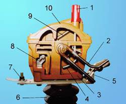
Sectional view of the extinguishing
chamber
| 
|
1. Closure of the filling opening with the gauge
and the air release valve
2. Control lever (made of stainless steel)
3. Bottom part of the extinguishing chamber (sectional
view)
4. Contact rod
5. Main contact
6. Supporting insulator
7. Connecting clamp with a screw
8. Auxiliary contact
9. Snap-action mechanism
10. Upper part of the extinguishing chamber (sectional
view) |
|